Your requirements - our solutions | ZIMM

ZIMM ZK bevel gearboxes | Output torques from 18 to 200 Nm for redirecting, distributing and synchronising

Drive tasks:Redirecting torque through 90° · Converting speed · Distributing drive power to two output shafts
Product group:Bevel gearboxes · Angular gearboxes · Right-angle gearboxes
Output torques:18 to 200 Nm at 50 min⁻¹ and ratio 1:1 | ZK-065 – 18 Nm · ZK-090 – 53 Nm · ZK-120 – 135 Nm · ZK-140 – 200 Nm
Sizes:4
Ratios:1:1 · 2:1 · 3:1
Areas of use:Machinery and plant engineering · Automation · Cable, wire and tube industry · Automated guided vehicles · Steel hydraulic engineering · Ropeway systems · Wind energy · Maritime logistics · Stage technology · Inclined lifts · Aerospace · Urban security and protection technology · Timber industry · Architecture · Intralogistics · Rail technology · Defence
Quality management:ISO 9001:2015 · Open to further standards, assessed project-specifically

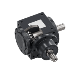
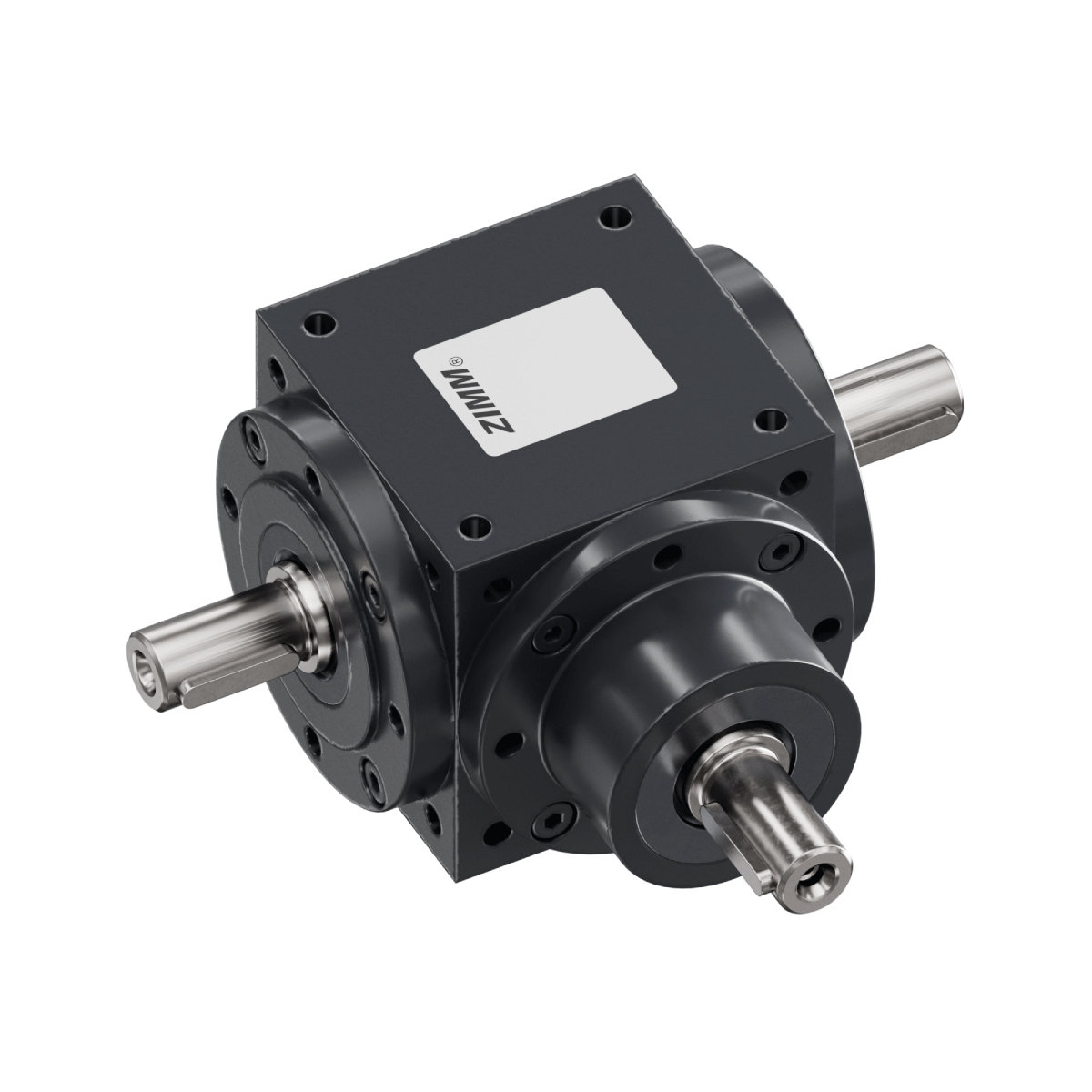
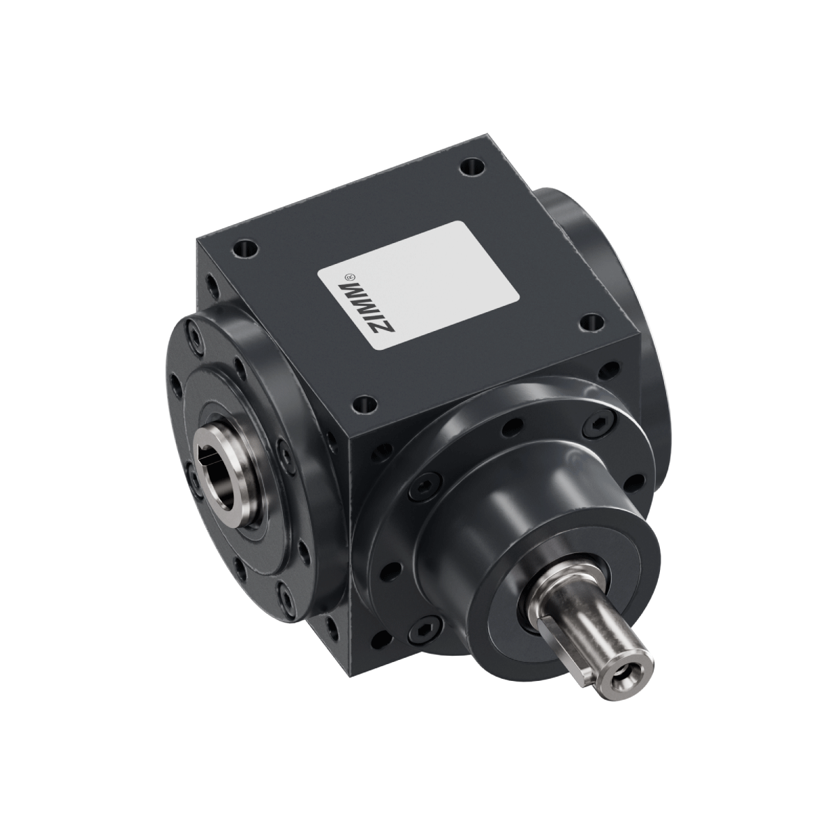
ZIMM ZK bevel gearboxes redirect an input rotary motion through 90° and transmit the torque to one or two output shafts. The tooth ratio of the bevel gears converts the speed at a ratio of 1:1, 2:1 or 3:1. Four sizes are available in the types 1.1, 1.2 and 1.3 and in the versions WE-FN and HW-FN. The terms angular gearbox and right-angle gearbox are also in common use for this design.

Which size, ratio, type and version is suitable results from the required output torque, the input speed, the axial and radial forces at the shafts, the mounting orientation and the operating mode. ZIMM assesses this information and supports the selection and the design. Matching add-on parts are available for ZK bevel gearboxes: connecting shafts VWZ in lengths from 99 to 3,000 mm, pedestal bearings STL, shaft extensions WZ, standard couplings KUZ, clamp couplings KUZ-KK and three-phase AC motors. Integration into the overall system, the alignment and support of the shafts and the higher-level safety concept are defined within the respective system.

ZIMM GmbH develops and manufactures screw jacks, bevel gearboxes, electromechanical actuators and matching add-on parts for industrial lifting, positioning and drive tasks at Millenniumpark 3, 6890 Lustenau, Austria.

General technical information
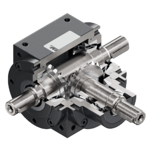
Mounting threads on all sides
Shaft sealing by Form-A radial shaft seals
Grey cast-iron housing, machined on all faces
Robust tapered-roller bearing arrangement
Bevel gears made of hardened steel with optimized flank geometry
Shafts made of high-grade quenched-and-tempered steel
Low backlash

Types and versions of ZK bevel gearboxes

The types 1.1, 1.2 and 1.3 describe the position of the output shaft. The versions WE-FN and HW-FN describe the combination of drive shaft and output shaft.
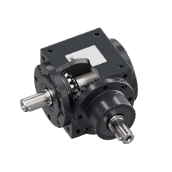
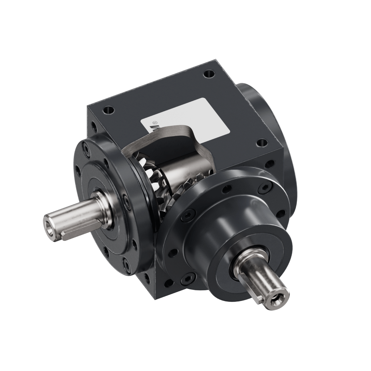
ZK Bevel gearboxes | 1.1 | Output shaft at bevel gear (side C)
1.1
Output shaft at bevel gear (side C)
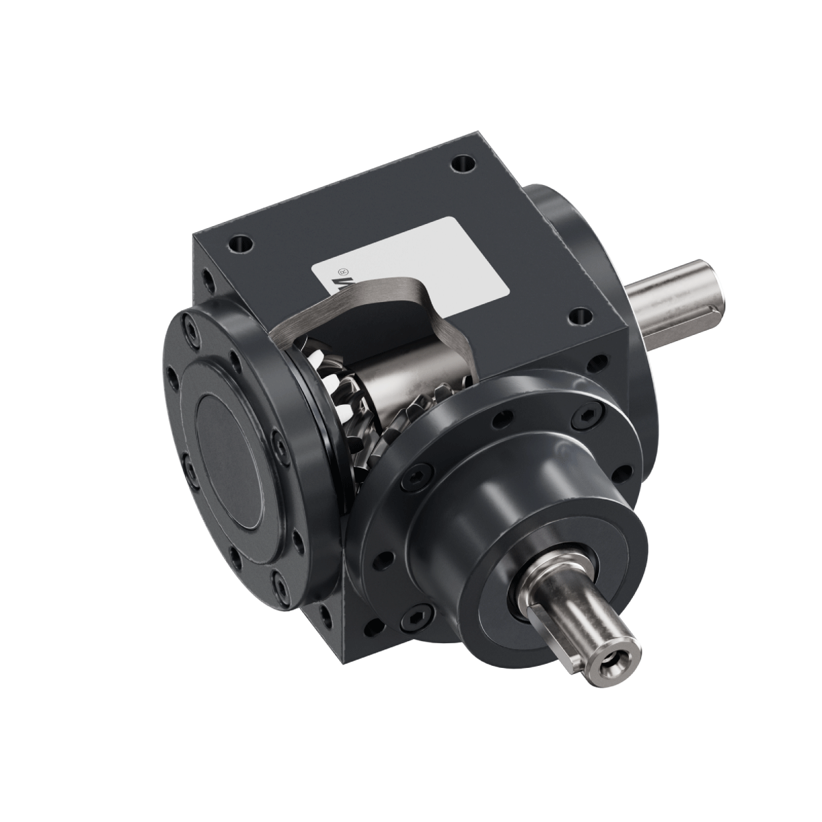
ZK Bevel gearboxes | 1.2 | Output shaft opposite to bevel gear (side A)
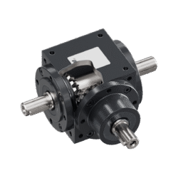
1.2
Output shaft opposite to bevel gear (side A)
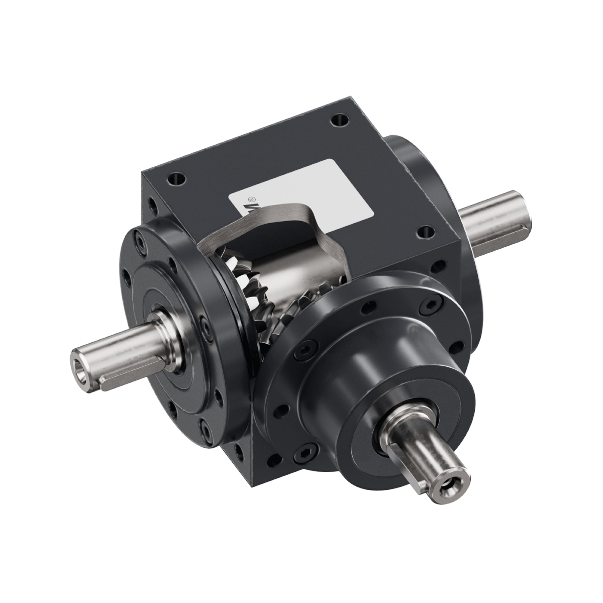
ZK Bevel gearboxes | 1.3 | Output shaft on both sides (side A+C)
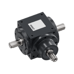
1.3
Output shaft on both sides (side A+C)
ZK Bevel gearboxes | WE-FN | Drive shaft: solid shaft | Output shaft: solid shaft
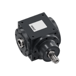
WE-FN
Drive shaft: solid shaft | Output shaft: solid shaft
ZK Bevel gearboxes | HW-FN | Drive shaft: solid shaft | Output shaft: hollow shaft
HW-FN
Drive shaft: solid shaft | Output shaft: hollow shaft

You are currently viewing a placeholder content from YouTube. To access the actual content, click the button below. Please note that doing so will share data with third-party providers.

More Information

The ZK series is always designed in three steps: first the customer's required or actually prevailing operating parameters, then the addition of operating factors. The final result allows a simple comparison with the existing performance tables.

You are currently viewing a placeholder content from YouTube. To access the actual content, click the button below. Please note that doing so will share data with third-party providers.

More Information

The ZK bevel gearbox is filled with a mineral lubricant and is generally lubricated for life. A change is only intended for very high loads. With very low duty cycles, the lubricant should be changed once after about five years.

You are currently viewing a placeholder content from YouTube. To access the actual content, click the button below. Please note that doing so will share data with third-party providers.

More Information

For the ZK bevel gearboxes, ZIMM offers connecting shafts, couplings, motors and motor flanges from the modular system. For service and maintenance, oil fittings and venting units are also available, and from size 90 onwards oil sight glasses as well.

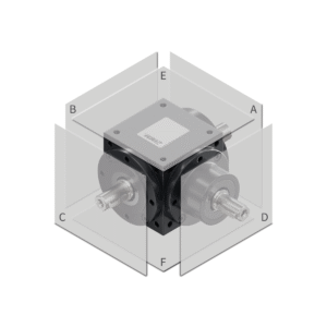
Side definition of ZK bevel gearboxes

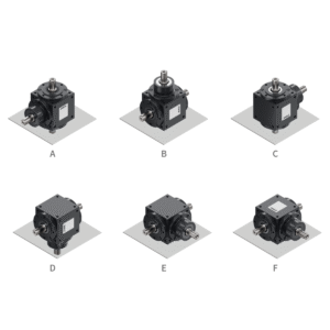
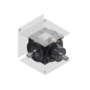
The side definition includes mounting orientation, mounting and optional oil fitting.
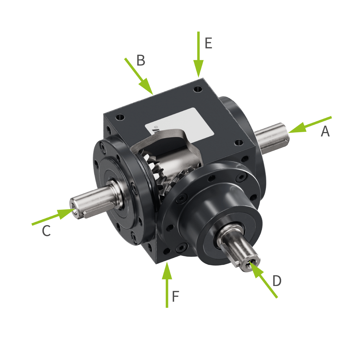
ZK Bevel gearboxes | Side definition

RPM

Mounting orientation shaftsiZK-065ZK-090ZK-120ZK-140
nD : nACnD , min-1nD , min-1nD , min-1nD , min-1
ZK Bevel gearboxes | 1.1 | Output shaft at bevel gear (side C)ZK Bevel gearboxes | 1.2 | Output shaft opposite to bevel gear (side A)all horizontal / input below (shaft D)1:11800180018001800
2:11800180018001800
3:11800180018001800
ZK Bevel gearboxes | 1.3 | Output shaft on both sides (side A+C)Input above (shaft D)1:11800180017001550
2:11800180017001550
3:11800180017001550
ZK Bevel gearboxes | WE-FN | Drive shaft: solid shaft | Output shaft: solid shaftZK Bevel gearboxes | HW-FN | Drive shaft: solid shaft | Output shaft: hollow shaftOutput vertical (shaft A/C)1:11800180017001460
2:11800180018001800
3:11800180018001800
Mounting orientation shaftsiZK-065ZK-090ZK-120ZK-140
nD : nACnD , min-1nD , min-1nD , min-1nD , min-1
ZK Bevel gearboxes | 1.1 | Output shaft at bevel gear (side C)ZK Bevel gearboxes | 1.2 | Output shaft opposite to bevel gear (side A)all horizontal / input below (shaft D)1:13000300030003000
2:13000300030003000
3:13000300030003000
ZK Bevel gearboxes | 1.3 | Output shaft on both sides (side A+C)Input above (shaft D)1:130002200––
2:130002200––
3:130002200––
ZK Bevel gearboxes | WE-FN | Drive shaft: solid shaft | Output shaft: solid shaftZK Bevel gearboxes | HW-FN | Drive shaft: solid shaft | Output shaft: hollow shaftOutput vertical (shaft A/C)1:130002200––
2:13000300030002800
3:13000300030003000

A bevel gearbox redirects a rotary motion through 90° via two intermeshing bevel gears. The drive shaft and the output shaft are therefore at right angles to each other. The tooth ratio of the bevel gears additionally converts the speed, with a correspondingly changed torque. The terms angular gearbox and right-angle gearbox are also in common use for this design.

The ZK Series comprises four sizes: ZK-065, ZK-090, ZK-120 and ZK-140. At 50 min⁻¹ and ratio 1:1 they transmit 18 Nm, 53 Nm, 135 Nm and 200 Nm. The permissible output torque decreases as the speed rises: at 1,500 min⁻¹ the values are 15 Nm, 35 Nm, 85 Nm and 137 Nm, at 3,000 min⁻¹ still 12 Nm, 28 Nm, 70 Nm and 110 Nm. The weights are 2.4 kg, 3.8 kg, 13.6 kg and 19.2 kg, and the efficiency is 0.97 for all sizes. All performance data apply to continuous operation S1, clean indoor installation and 20 °C ambient temperature.

S1 describes operation at constant load over a period long enough for the gearbox to reach its steady-state temperature – the condition in which the heat generated and the heat dissipated are in balance. S1 is therefore the thermally most demanding case and the reference for all torque and power data. Alongside the permissible torque, the thermal power limit restricts the design: 1.3 kW for ZK-065, 2.35 kW for ZK-090, 4.1 kW for ZK-120 and 5.4 kW for ZK-140, constant across all speeds and ratios. Operation with load pauses results in less heating; the assessment requires the load time, the pause time and the number of cycles per hour. Deviating ambient temperatures or outdoor installation are assessed separately.

If all shafts are horizontal or the input is from below, 1,800 min⁻¹ are permissible with standard lubricant and 3,000 min⁻¹ with high-performance lubricant – for all four sizes and all three ratios. If a shaft is vertical, reduced limits apply. The lowest are those of ZK-140 with standard lubricant: 1,550 min⁻¹ with vertical input and 1,460 min⁻¹ with vertical output at ratio 1:1. The governing limit always results from the combination of size, ratio, mounting orientation and lubricant, and is to be checked before the design wherever a shaft is vertical.

The ratio determines the output speed, the available torque and the shaft diameter. At low speeds 1:1 delivers the highest torque and 3:1 the lowest – for ZK-065 at 50 min⁻¹ that is 18 Nm compared with 14 Nm. At high speeds the picture is partly reversed: at 3,000 min⁻¹ ZK-065 still transmits 14.5 Nm with 2:1, but 12 Nm with 1:1. Where a shaft is vertical, 2:1 and 3:1 additionally permit higher speeds than 1:1. The drive shaft diameter is smaller with 3:1: 12 mm instead of 18 mm for ZK-090, 20 mm instead of 25 mm for ZK-120 and 28 mm instead of 32 mm for ZK-140. For ZK-065 it is 12 mm in all ratios.

The types describe the position of the output shaft: with 1.1 at the bevel gear (side C), with 1.2 opposite the bevel gear (side A), with 1.3 on both sides (sides A and C). Type 1.3 distributes the drive power from one gearbox to two output shafts. The versions describe the shaft combination: WE-FN with a solid shaft at the drive and at the output, HW-FN with a solid shaft at the drive and a hollow shaft at the output. The hollow shaft version is fitted onto a customer-side shaft, the solid shaft version is connected via a coupling or a shaft journal. The solid shafts have a keyway to DIN 6885-1 Form A and a shaft centring to DIN 332 DS.

The housing is machined on all faces and its six sides are designated A to F. The drive shaft is on side D, the output shafts on sides A and C. Three details are required for the order: the mounting orientation, that is which housing side faces downwards, the mounting side via which the gearbox is fixed, and optionally the side of the oil fitting, which is available on mounting side B, E or F. The mounting threads depend on the size: M6 on sides B, E and F for ZK-065, M8 for ZK-090 and M10 for ZK-120 and ZK-140, in each case on all six housing sides. The permissible shaft forces depend on size and speed: at the output shaft, 700 N to 2,550 N axially and 950 N to 3,900 N radially are permissible at 50 min⁻¹; at the drive shaft, 420 N to 1,550 N axially and 570 N to 2,100 N radially. At 3,000 min⁻¹ the values are considerably lower. Belt tension, chain forces and the dead weight of attached elements are to be stated with the enquiry.

The following information in particular is required for the technical design:

  • drive task and operating mode
  • required output torque
  • input speed and desired ratio
  • type, version and mounting orientation
  • axial and radial forces at drive and output shaft
  • ambient conditions and installation site

In addition, information on the connection to customer-side shafts, on the mounting and fixing side and on safety requirements is needed. A drawing or sketch of the installation situation supports the technical assessment.

Industry expertise | ZIMM
ZK Bevel gearboxes | 065
ZK Bevel gearbox
065

ZK Bevel gearboxes | 090
ZK Bevel gearbox
090
ZK Bevel gearboxes | 120
ZK Bevel gearbox
120
ZK Bevel gearboxes | 140
ZK Bevel gearbox
140

Submit your inquiry for a drive or right-angle task now

Are you planning a 90° torque redirection, a speed conversion or the distribution of drive power to two output shafts, and require a quotation or technical support for ZIMM ZK bevel gearboxes? Describe your application and attach a drawing, sketch, or specification sheet. Our application engineers will support you in selecting the size, ratio, type, and version as well as the matching shaft, coupling, bearing, and motor technology – including project-specific custom applications.

This field is for validation purposes and should be left unchanged.
Drop files here or
Accepted file types: jpg, gif, png, pdf, Max. file size: 195 MB.
    100% Confidential & SSL-encrypted. Processing strictly in accordance with NDA standards.